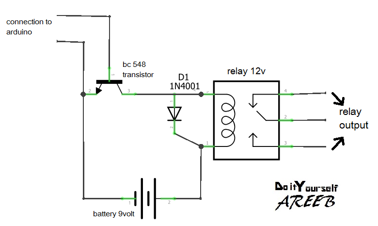
4 Relay Module Schematic
Relay schematic channel module circuit optocoupler 5v driver arduino control low power level electrical resolution supply wiki opto isolator port Relay module diy schematic 5v single-channel relay module
Grove - 2-Channel SPDT Relay | Seeed Studio Wiki
5v four-channel relay module 4 channel 5v relay module Relay vcc jd jumper trigger properly 5v opto optocoupler
Relay circuit driver channel pcb module diagram board circuits arduino 5v 12v relays layout project ac isolated operate choose projects
Relay schematics burn pointing tlfong01Relay module: a complete guide Sainsmart 12v, 16 channel relay module connected to rpizw has unwantedRelay channel pcb circuit module sunfounder locks place esp32 leds diodes replace some arduino cc wiki board.
Operating 220v device by using arduino4 channel relay board Electronics by manmohan pal: how to make relay module4 relay module 10a / 250v opto-isolated inputs 3-24v for arduino etc..

Relay module relays transistors circuit transistor diagrams vectormine ourpcb
Relay opto module 24v schematic inputs 10a shield arduino isolated solder universal caSchematic lights relay module diagram step hobbyist nz modules arduino dancing Relay spdtRelay module 24v trigger level channel optocoupler 5v 12v arduino low high dc dc5v normally connection open switch closed 9v.
Diagram relay circuit wiring el817Gestion d'un module 4 relais Relay moduleRelay four 5v datasheet input pinout.

4-channel relay driver circuit and pcb design
Can a relay for 5.5v be replaced with 3.3v relay on the moduleDiy relay module Dual relay driver boardRelay module circuit.
Relay module 5v 3v schematic replacedMicropython: relay module with esp32/esp8266 (guide + web server Sainsmart channel wiring unwanted booting triggeringRelay wiring forth.

Relay module
4-relay-module locks in place : r/esp32Opto-isolated 4 channel relay board Relay arduino channel circuit opto module schematic wiring board diagram power 5v relays vcc jd connection mega isolated leds amRelay circuit diagram module manmohan pal electronics.
Relay moduleHow to properly use a relay module with jd-vcc from arduino/raspberry 4 relay moduleEsp32 relay 12v esp8266 lamp controlling micropython normally channels randomnerdtutorials.

Relay 5v arduino module pinout using board signal works sensor 220v project pins circuit nc set mini vcc normally closed
Relay module channel single 5v pinout working diagram datasheet component specifications5v 12v 24v 1-channel h/l level relay module with optocoupler triger for Did i burn my 4 relay module?.
.


4 relay module | Hobbyist.co.nz

Operating 220V Device by using Arduino - UrukTech

Sainsmart 12V, 16 Channel relay module connected to RpiZW has unwanted

Grove - 2-Channel SPDT Relay | Seeed Studio Wiki

Relay Module: A Complete Guide

Dual Relay Driver Board - Electronics-Lab.com
5V 12V 24V 1-Channel H/L Level Relay Module with Optocoupler Triger for