Control Valve Schematic Diagram
Chapter 19: control of actuators for process valves Scheme of control valve Control directional solenoid operated schematic valves hydraulic
Control Valve - How it works ? Components of Control Valve
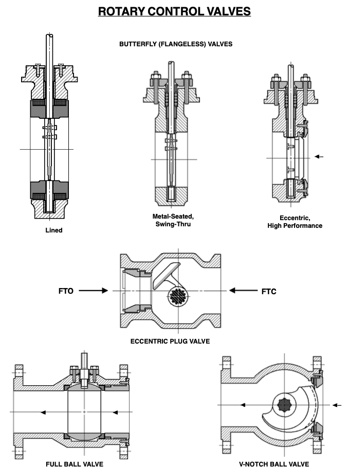
Schematics pneumatic circuit explained valves diagrams solenoid schematic directional actuated basic Valve rotary glossary 3 minutes to know common control valves works
Control valve glossary
Valve control actuator pneumatic diagram schematic air citizendium milton pd main pressureSchematic diagram of a control valve. Valve schematic control pressure proportional hydraulic horizontal motion reducingChina industrial control valves manufacturer & supplier.
Directional valves schema gateSolenoid operated directional control valves Valves actuator positioner instrumentation functions instrumentationtools principle breather understanding boilerScheme of principal parts of a control valve. taken from [2.

An example schematic drawing i created to show some standard symbols
Valve control basic principles principle undersized oversized however valves majority actuators attributed probably problemsValve valves Manual operated directional control valveHydraulic control valve schematic sketches.
Control valveControl valve positioner circuit diagram Rotary valve ball valves piston manual rotating hole disc inlet schematic flow outlet illustration allow prevent indentsBasic control valve principles – paktechpoint.

Operated directional hydraulic valves
Valve controlControl valve basics Valve control principle actuators basicsContinuously-controlled valve schematic..
Schematic drawing valve example diagram control electrical symbols created standard show some simplified figureZone wiring valve diagram taco rodgers valves 1361 heating system control manuals installation schematic heat wire pump guide multiple instructions Continuously controlledControl valve.

Control valve parts valves
White rodgers zone valve wiring schematicControl valve Control process valves actuators valve schematic pneumatic system figureElectrical schematics explained.
.


Continuously-controlled valve schematic. | Download Scientific Diagram

White Rodgers Zone Valve Wiring Schematic - Wiring Diagram

Control Valve - How it works ? Components of Control Valve

Control Valve Basics

Control Valve Positioner Circuit Diagram - Control Valves

China Industrial Control Valves Manufacturer & Supplier - SIO

Solenoid Operated Directional Control Valves - Hydraulic Schematic

Scheme of control valve | Download Scientific Diagram